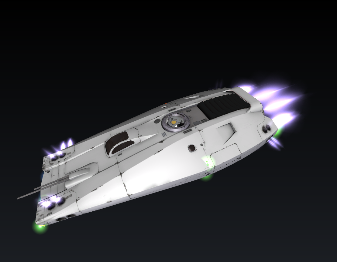
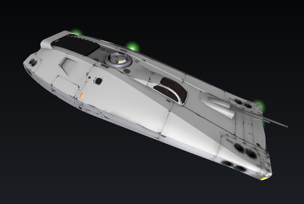
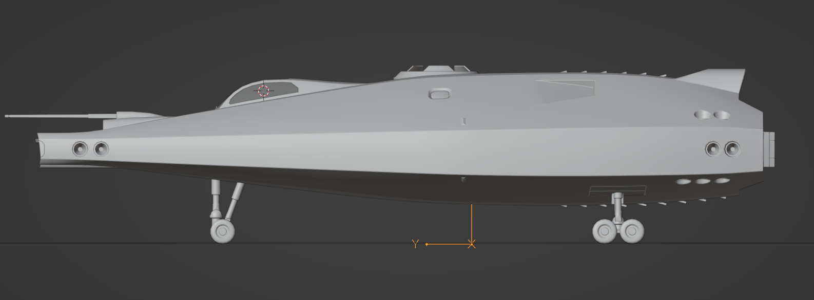
Appearance
Model system overview
tl;dr: a simple scenegraph-based approach with some animation support.
Some of this information applies to every kind of mesh (ship, staction, etc), but some are more specific to ships or stations. You can omit those things from a building model for example.
Model setup
For the game to detect the model, its files (meshes, textures, ship.model) need to be placed into specific directories in Pioneer/data. All assets have their subdirectory in one of these:
- data/models/ - model files all live here
- buildings/ - planetside buildings
- cockpits/ - cockpit models
- misc/ - miscleanous things, like escape pods, cargo containers, etc
- ships/ - spaceships
- stations/ - orbital stations
- weapons/ - missiles, guns and such
While the game doesn't really care which subdirectories of models/ these are, it is preferable to put them in their proper place for clarity.
Ships and stations, buildings and their properties then need to be set up with json files in their repsective directories inside Pioneer/data. Descriptions of these jsons are linked bellow:
- data/
- ships/ - for spaceships
- stations/ - for orbital and ground stations
- configs/buildings/default.json - defines buildings, and how the city generation uses them.
Importing models
We are using the Assimp importer, which theoretically supports many different formats but you are expected to use only some:
When node structure, node names and animations matter, use Collada (.dae).(subject to change in the near future to gltf)
Export settings (useful to save them as a preset:
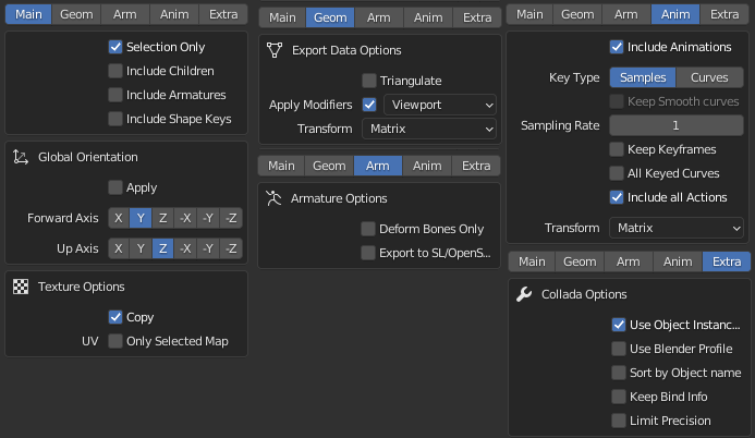
- For models that does not have animation, the
[ ] Include animationscan be turned off.
- For models that does not have animation, the
For static geometry, such as buildings, OBJ is recommended, this may allow for some optimizations
The only officially tested 3D modelling program at the moment is Blender 3.4. For blender, a quick checklist is:
- Coordinates: X right, Y forward, Z up:
- Always generate UV coordinates for the model
- Versions downloaded from blender.org support Collada out of the box, while the version distributed with some Linux distros doesn't.
- There is an alternative Collada exporter made by the Godot team.
Model definition file
Models must be placed under data/models, preferably in their respective categories (ships, cockpits, buildings, etc).
To define a model, create a name_here.model text file next to your exported mesh. You can use the example above as a template:
sh
version 2 # Required to start the file

# Comments can be written like this
# Define all used materials first
material "some-material" {
	shader "multi"
	diffuse 0.8 0.7 0.7
	specular 0.3 0.3 0.3
	shininess 40
	texture diffuse  "diffuse_texture.png"
	texture specular "specular_texture.png"
	texture normal   "normal_map_texture.png"
	texture glow     "glow_texture.png"
	use_patterns
}

# Meshes to be imported into this model, should be in the current folder
# Mixing different formats should be OK
# Level of Detail levels are set up like this:
lod 300 {
	mesh "fuselage_hi.dae"
	mesh "engines_hi.dae"
}

lod 150 {
	mesh "fuselage_mid.dae"
	mesh "engines_mid.dae"
}

lod 50 {
	mesh "fuselage_low.dae"
	mesh "engines_low.dae"
}

# Collision mesh:
collision "ship_collision.dae"

#Animations are defined like this:
#anim name, first frame, last frame
anim "gear_down" 1 100
anim "idle" 101 201
Materials
Only material names are imported from the 3D models, so you need to set up the material properties and used textures in the .model file like this:
sh
material "material_name" {
	shader "multi"
	diffuse 0.8 0.7 0.7
	specular 0.3 0.3 0.3
	shininess 40
	texture diffuse  "diffuse_texture.png"
	texture specular "specular_texture.png"
	texture normal   "normal_map_texture.png"
	texture glow     "glow_texture.png"
}
If the texture is in the same directory as the .model file, then only the filename is needed. You can also use textures from other directories via relative paths:
sh
texture diffuse "diffuse_texture.png"
# OR
texture diffuse "../othership/other_texture.png"
# OR, relative to the root of the data/ directory
texture diffuse "/models/ships/othership/other_texture.png"
../ means one level above in the directory structure, and you can string them together: ../../
Material properties
| Keyword | Description |
|---|---|
| material | Name. Mandatory! If exporting from Blender, you can use the name of the Material as is. It's case-sensitive.(If in doubt, note that both .obj and .dae files are human readable, and you can find the assigned names in them with a text editor.) |
| shader | Shader used to render this material. Optional, defaults to "multi" if not specified. Shaders are defined in .shaderdef files in data/shaders/. |
| diffuse | Diffuse colour RGB. Default white. |
| specular | Colour of specular highlights, RGB. Default white. Set to black to disable highlights. |
| emissive | Self-illumination colour, RGB. Default black. |
| shininess | Sharpness/size of specular highlights, 0 - 128. Default 100. (Inverse of Roughness value of Blender) |
| opacity | 0-100, controls transparency of the material. A node with a material opacity less than 100 is treated as transparent, otherwise opaque. |
| use_patterns | This material will use the pattern/colour system. Read more below. |
| unlit | No lighting, diffuse value can still be used to tint the result |
| alpha_test | Pixels with alpha value < 0.5 are discarded, this is good for fences and such. It produces sharp edges but the geometry does not need to be sorted. |
| render_state | Specifies the render state used to draw this material. Used to control how transparent materials (e.g. cockpit canopies) are drawn. |
Textures
Textures are assigned to a material with a texture <binding> "<path>" directive. Textures can be bound to any texture binding point specified by the shader. The default multi shader supports five binding points:
| Binding | Description |
|---|---|
| diffuse | Diffuse texture, file name If you don't specify this, a white dummy texture is generated. |
| ambient | Ambient occlusion texture, file name (in the same folder). Used for faking ambient occlusion, by multiplying the diffuse with this. So the darker the AO texture, the darker it will make the diffuse. |
| glow | Self-illumination texture, overrides emissive colour parameter. Default none. |
| specular | Specular highlight colour/intensity texture. Default none. Multiplied by specular colour parameter, so set it to white to leave control entirely to the texture. |
| normal | Normal map. Default none. You can create surface detail with it, which interacts with lighting. |
Render State
You can specify certain aspects of the internal render state used to draw a material. These properties are mostly for advanced users and are documented here briefly. The following render_state block is sufficient to set up a transparent material:
sh
material "mymaterial" {
	# ...
	opacity 40

	render_state {
		blend alpha
		depth_write off
	}
}| State | Description |
|---|---|
| blend | One of solid, additive, alpha, alpha_one, alpha_premult. Controls the blending function used to render the material. Alpha blending should be used with transparent materials. |
| cull | One of front, back, none. Controls the cull mode used to determine which side of a triangle is considered visible. None renders the material as "two-sided". |
| depth_test | Either on/off. Default on. Controls whether the material uses depth-tested rendering or always renders over top other objects in the scene. |
| depth_write | Either on/off. Default on. Controls whether the material writes the fragment depth to the depth buffer (should be off for transparent materials). |
| scissor_test | Either on/off. Default off. Scissor is only used for UI rendering at this time. |
Textures
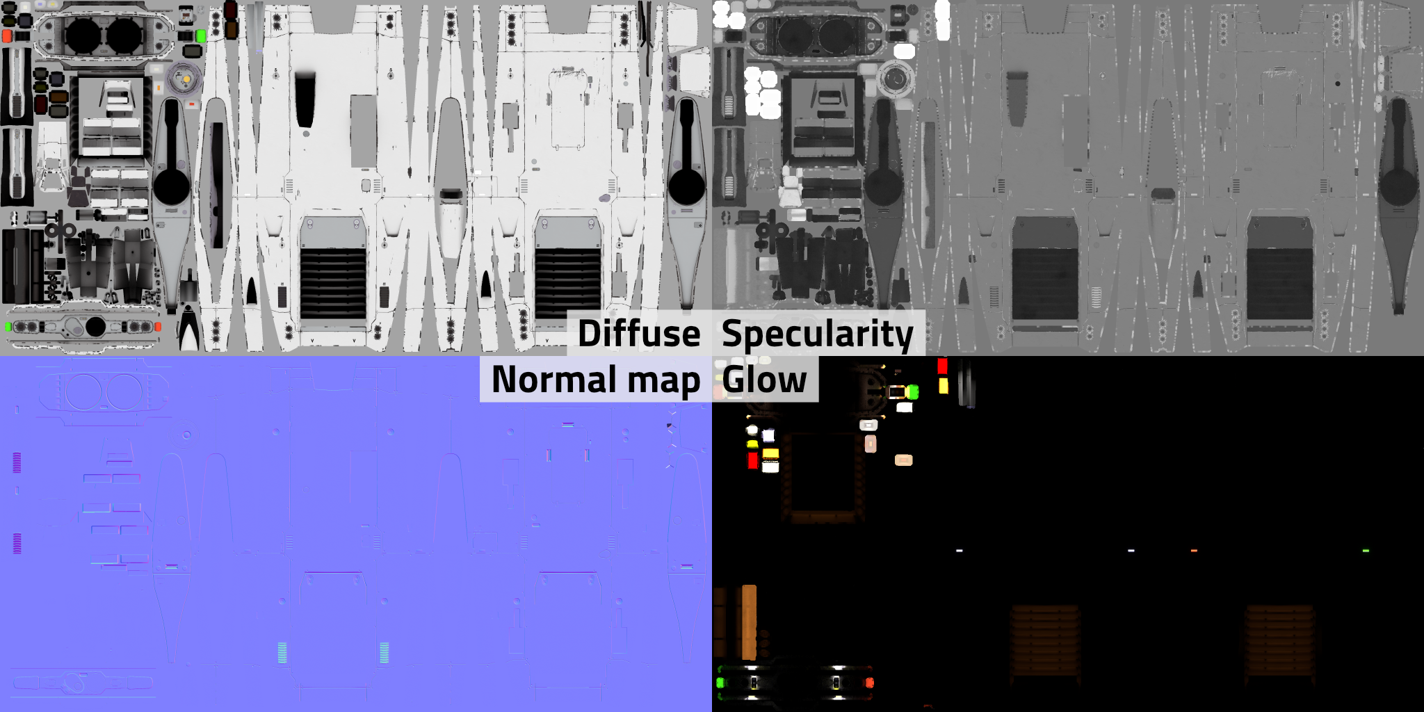
Textures preferably have power of two dimensions (256, 512, 1024, 2048 etc.), but they don't need to be square as long as the two dimensions are still power of two. 2048*1024 for dimensions are fine for example. The above example shows the diff, spec, norm and glow map of the Sinonatrix (which also has another set for its engines and some other details)
Patterns
A system to mark customziable color areas on the model without splitting it to separate materials. The player can apply these patterns with custom colors to their ships in the Paint shop found in the Repair services tab on stations.
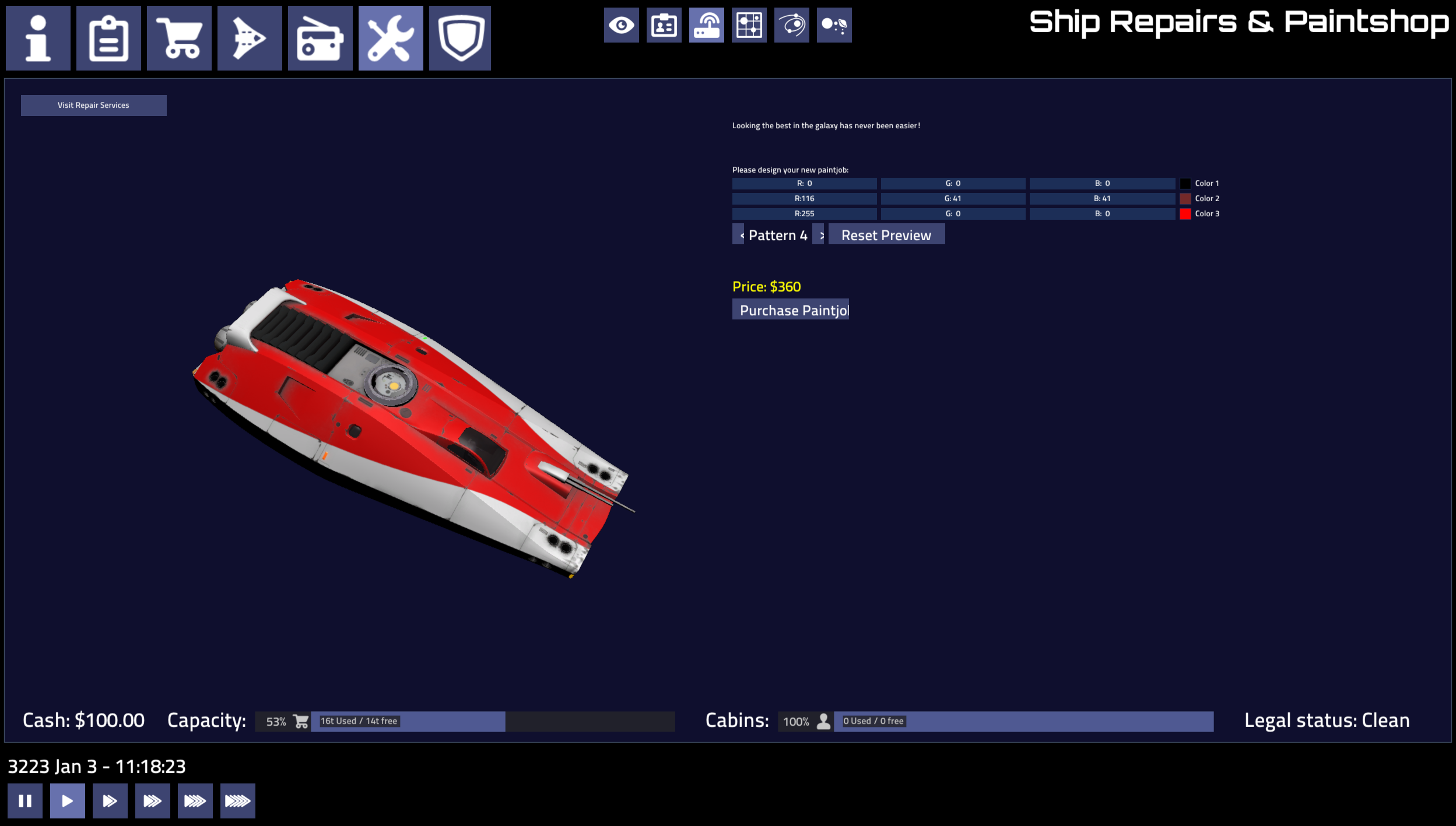
Patterns are small grayscale textures placed in the model folder, named pattern*.png. Using gray or white colour you can mark the areas tinted by one of the customizable colours (black marks unaffected areas). The colours are set by the game (faction-specific ship colours, shipyard UI for the player).
The value ranges are:
- 0-63: not affecting (black)
- 64-127: first color (dark gray)
- 128-191: second color (mid gray)
- 192-255: third color (light gray/white)
You can set all three channels to these in RGB, or only the L channel in HSL (Hue, Saturation, Level) to get the needed gray.
The alpha channel of the pattern defines it's transparency. It can be used for gradual changes from colored to blank, but not for gradients between different gray ranges. Useful for showing wear on the pattern, or coloring some parts more lightly. Alpha channel can be created by using a layer mask.
Antialiasing (which generates small gradients) can cause artifacts, especially at black-white boundaries. To avoid it, try lowering the contrast on problematic places. Even different grays can be used from the same range, they will indicate the same color.
The system has several limitations: it is not meant to do fine details, transitioning from one color to another is sharp and it works best with white/light textures. You'll have to experiment.
Detail levels (LoD)
Meshes are assigned to detail levels using the lod pixelsize directive:
sh
lod 100 {
	mesh "hull_low.dae"
}

lod 200 {
	mesh "hull_med.dae"
}

lod 1000 {
	mesh "hull_hi.dae"
	mesh "landing_gear.dae"
}
A detail level will be picked if the approximate radius of the model on screen is less than pixelsize (for the highest level it does not matter as long as it's larger than the others). Use the modelviewer to find optimal sizes.
You may specify any number of detail levels in any order, they will be sorted according to size.
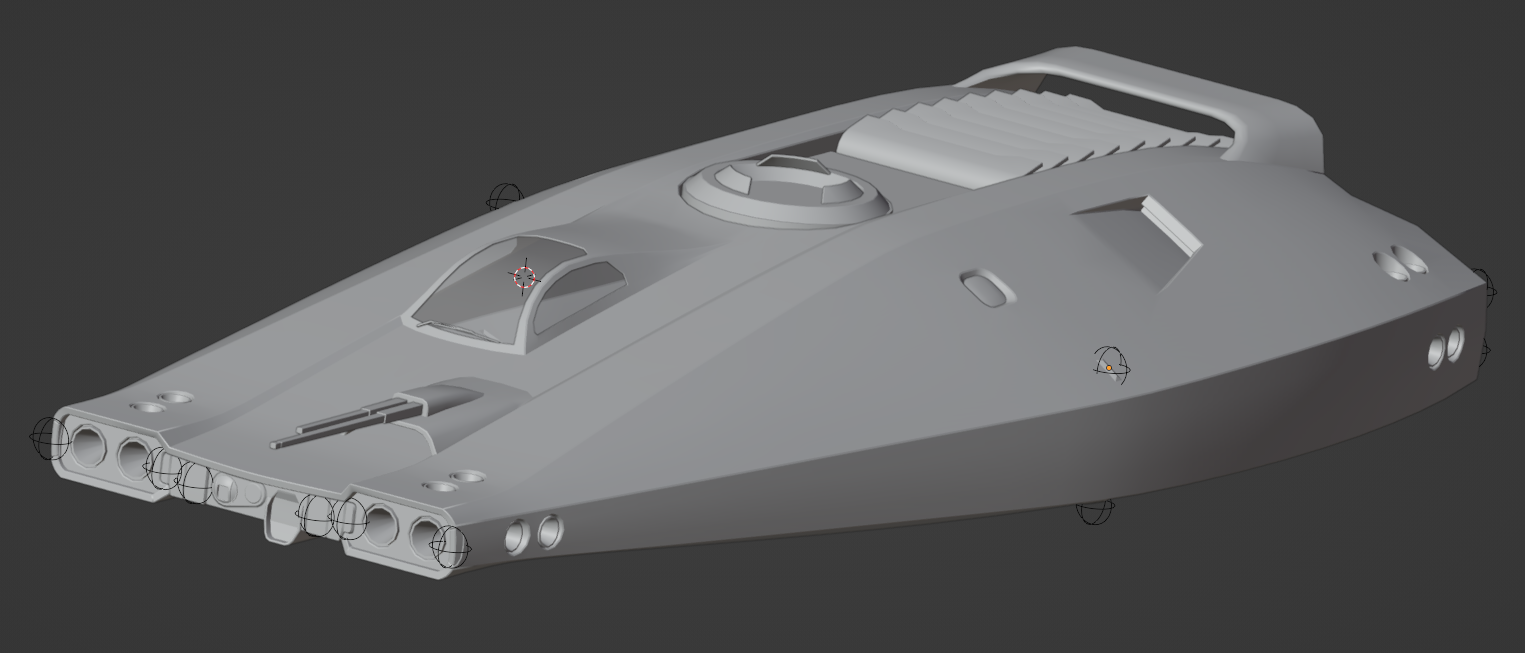
Shield and collision meshes
These are special meshes defining collision, and how the shield is shown (and hit).
Shield
Shield meshes must be stored in a separate mesh file. The shield model selected for a ship is controlled by the shield_model key in the ship definition JSON file.
All objects in a shield mesh file will be considered shield geometry. Shields should be in their own mesh files and be loaded by an associated model file:
sh
version 2 # my_ship_shield.model

lod 100 {
	mesh "ship_shield.dae"
}
That model file needs to be specified in the ship's ship.json file via the shield_model key for it to be loaded. If the shield_model key is not present, it will fall back to the name of the ship's model with a _shield suffix added.
json
{
"model": "my_ship",
"shield_model": "my_ship_shield"
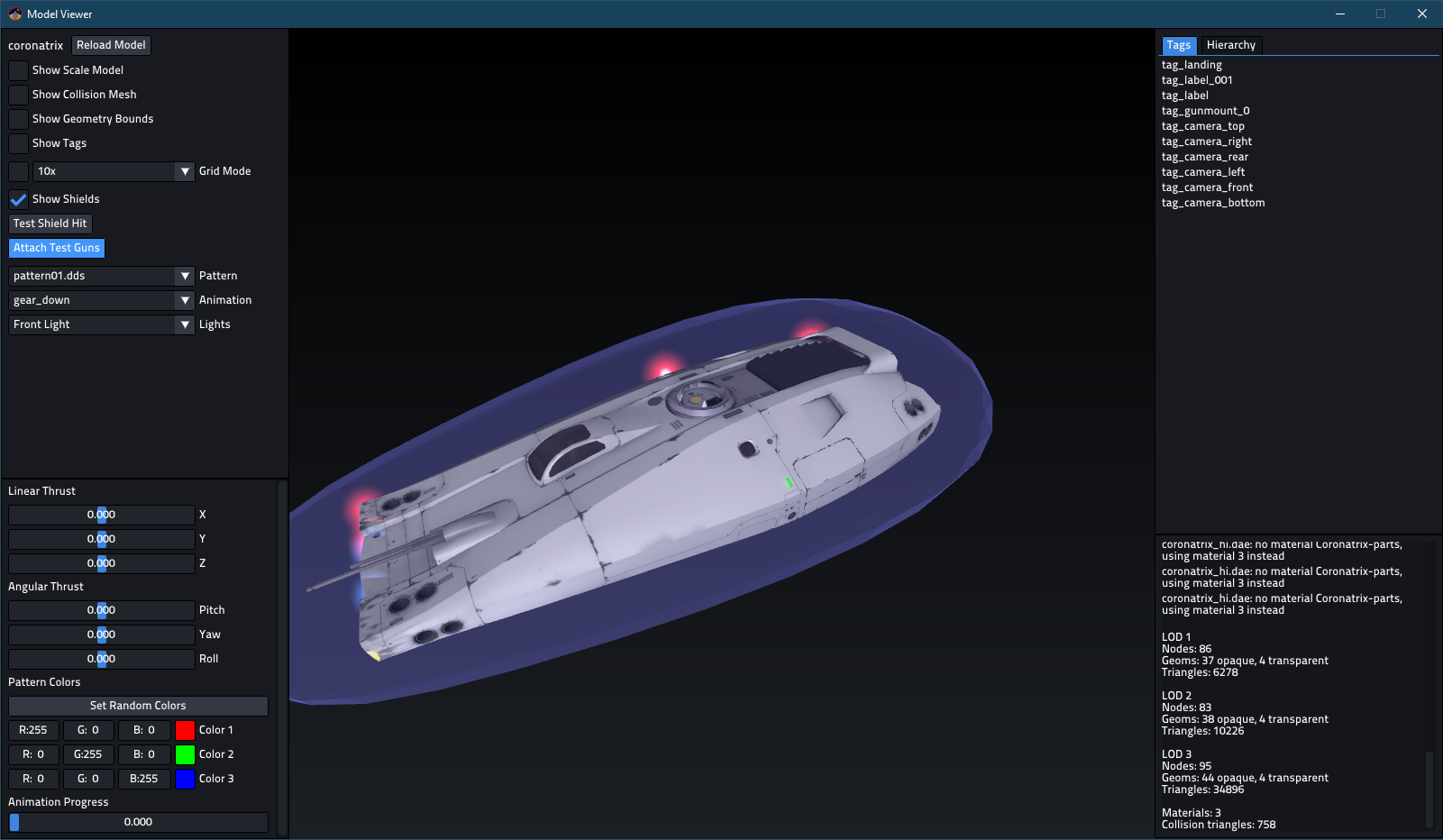
}If set up correctly, you'll be able to see a shield on the ship model when toggling the Show Shields option in the Model Viewer.
Collision
Collision meshes can be in separate mesh files, or included in the high LoD mesh file.
By default, the collision mesh of a model is the bounding box of all the meshes.
For more control, name objects with the prefix collision_ and they will be added to form a collision mesh (these objects will not be visible geometry, and the bounding box will not be generated).
Note, these names are reserved for station collision trigger surfaces:
- collision_pad1
- collision_pad2
- collision_pad3
- collision_pad4
- etc
You can also import a separate mesh using the collision directive in the model definition:
sh
collision "collision.obj"The collision mesh is separate from all detail levels, so it should be only defined once.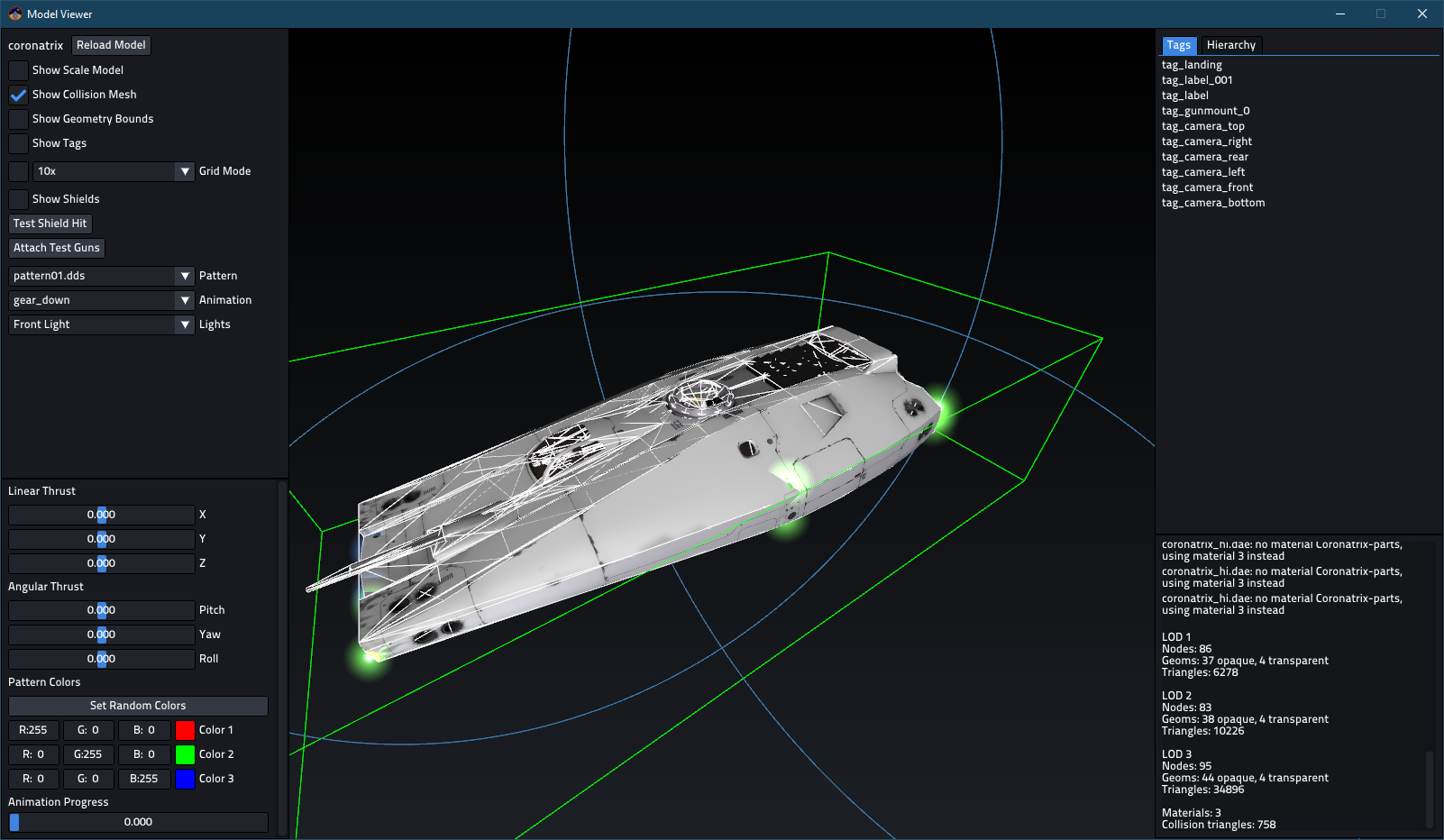
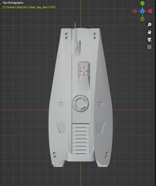
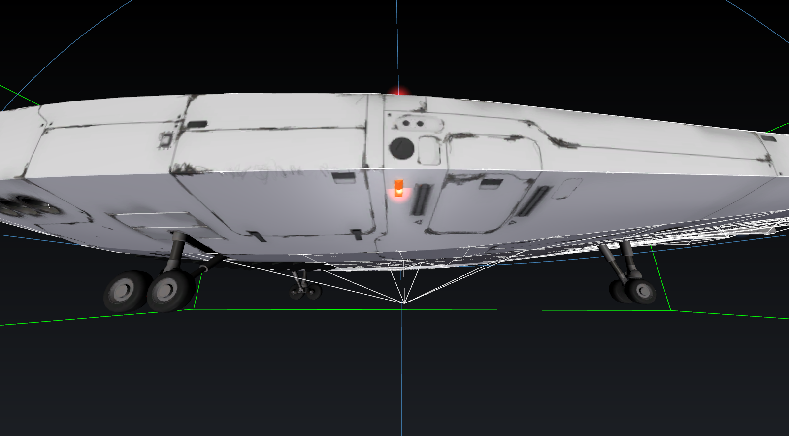
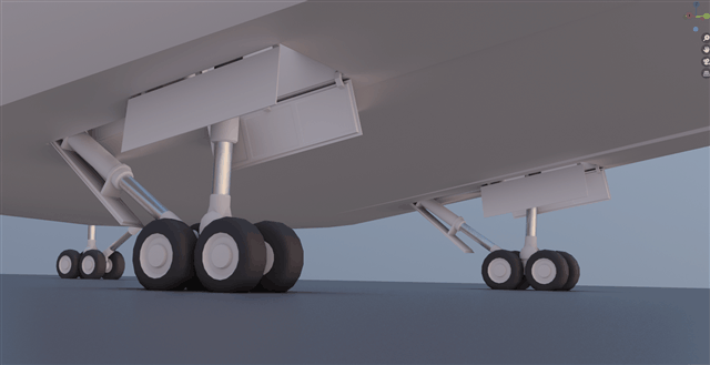
Collision meshes are also used to detect if the ship has landed. You need to extend a little bit of the mesh to the level of the gears for proper detection:
Decals
Decals are meant for customizable insignia on spaceships and changing advertisements on space stations. Up to four unique decals are available for a model (multiple identical decals are allowed). Place a piece of geometry, usually a flat quad, with proper UV coordinates and name it decal_01, 02, 03 or 04. The game will then use a special material on the geometry, or make it invisible if no decal is to be used.
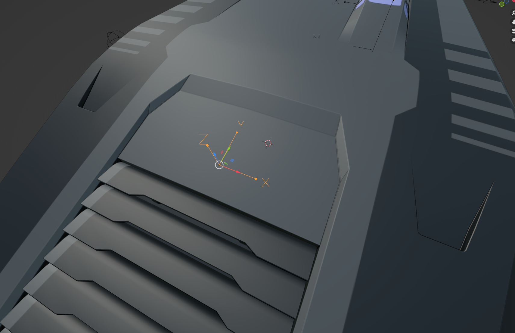
Tags
Models have special "tag points" marked with specifically named empty objects in Blender. They define thruster, lights and camera placement, weapon fire location and so on.
These special nodes are only imported from the most detailed LOD, there is no need to duplicate them. They are rendered outside the detail level system.
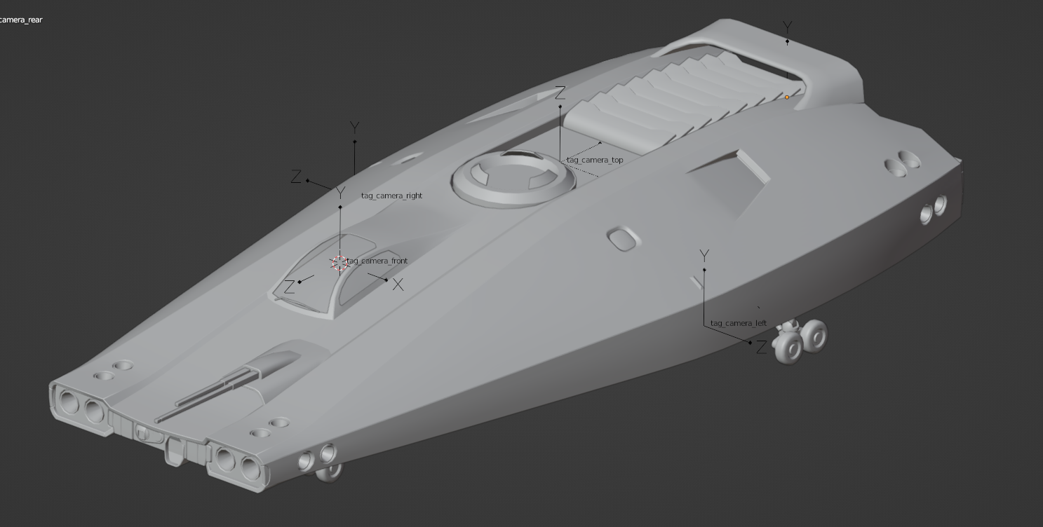
Cameras
These define the position and orientation of the six internal view cameras. If one is missing, tag_camera will be used with its orientation adjusted for the appropriate view direction. If there's none, ship center is used.
Camera tag scale should be 1 on all three axes to avoid glitches!
Their orientation is: Z - out, X - left, Y - up:
Their names are self-explanatory, and they are preferably placed in the cockpit, or onto sensors visible on the model:
tag_camera- fallback for missing camera tagstag_camera_fronttag_camera_reartag_camera_lefttag_camera_righttag_camera_toptag_camera_bottom
Thrusters
Preferred display mode for these empties is Single Arrow, which shows only the Z axis:
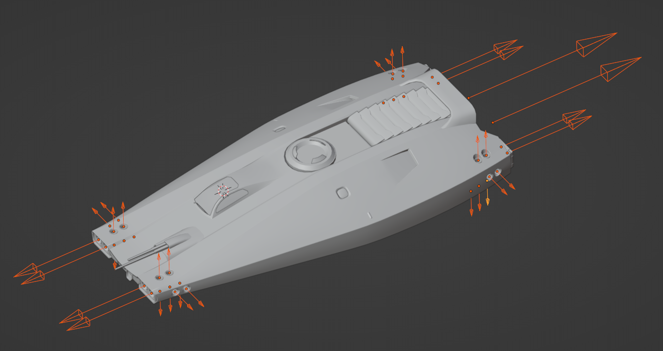
Thruster size is taken from the object scale. Begin the object name with either:
thruster_- lights up both for turning and translationthruster_linear- only lights up for translation
The game determines which thrusters should fire automatically based on their location and orientation.
Thruster colour can be modified, see: https://github.com/pioneerspacesim/pioneer/pull/3948 (not working currently)
Billboard lights
Simple light sprites placed using empty nodes with special naming navlight_*. Their scale defines the size of the light. Orientation does not matter.
This feature will be more customizable someday, but for now the following name prefixes are recognized:
navlight_red: blinking red light, with ships when landing gear is down. On stations it is on constantlynavlight_green: blinking green light when landing gear is downnavlight_is blue, on when landing gear is down.space stations,
navlight_pad<number>lights change according to landing pad reservation status
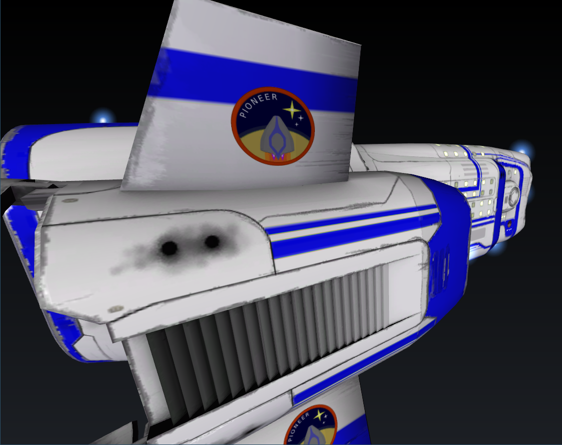
Labels
Dynamic 3D labels are meant for naming ships and space stations. Put an empty object in the model and give it a name beginning with label. The text is set by the game at runtime if supported. Important: not "tag_label" but "label."!
Node scale can be used as usual but the text is not constrained to the node bounds or anything like that, so some trial will be required.
You can use multiple label nodes but they will all show the same text.
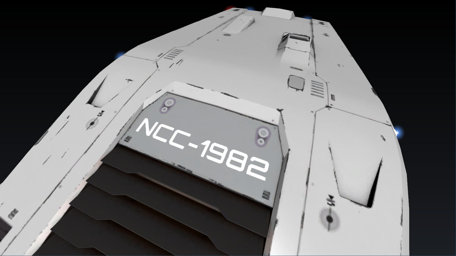
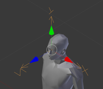
The tags orientation defines the direction of the text: Z out, X right, Y up:
Landing tag
Named tag_landing, it defines the placement of the ship while landed. Basically shows ground level:
Important note: this tag is not used for landing detection. You need to add a bit of collision mesh extending to this height to allow the ship to land.
Guns
These can define the point where the weapon projectiles are shot from.
tag_gunmount_0_multi_0andtag_gunmount_0_multi_1- front guntag_gunmount_1_multi_0andtag_gunmount_1_multi_1- rear gun
The _multi_# part sets up the two nozzles of double barreled guns, for single barrel guns, _multi_0 is used. tag_gunmount_# can be used too, then you don't set up the second barrel at all, and they will shoot at a slight offset.
Animations
Set up in the model file with their starting and end frames:
anim "gear_down" 1 100An animation consists of Channels. Each channel controls one node (always a MatrixTransform) and has a list of position and rotation Keys. Each key has a time and value. Keys are always linearly interpolated.
Because of the linear interpolation, it is advised to bake animations (TODO: baking guide), so easings are preserved. This is especially important for more complex animations:
There are two animations supported currently:
"idle"- a looping animation. Good for rotating sections, radar dishes, windmills for example"gear_down"- lowering of the langing gear. Frame 0 is fully raised, the endframe is when it is fully lowered. Played backwards for raising the gear.
At first the animations had proper play/pause/loop functionality but right now it is not so. Animation progress (and fun things like serialization) needs to be controlled directly by whatever feature uses the animation (see: landing gear).
Debuging models
You can access some in-game model debug functionality via the debug menu accessed via ctrl+i:
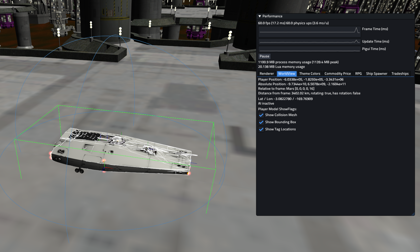
Modelviewer
Additionally Pioneer provides a model viewer with even more functionality like shield display, and an error log. This can be accessed by launching editor.exe from where Pioneer is installed.

It can be helpful to place a shortcut to the model directory while working on it, so one can quickly check it out.
Internal workings
You can find some testcase models at https://github.com/Luomu/newmodels.
The internal scene graph consists of several of these nodes:
| Node | Base class. A node can have a name and one or more parents. |
|---|---|
| Group | A group is a Node that can have several children. |
| MatrixTransform | A Group that applies a transformation to its child nodes when rendering. |
| Tag | A named point on the model for use by external code, like cameras or weapons. Tags can be animated if needed. |
| StaticGeometry | Contains one or more StaticMeshes. |
| LOD | Detail level control node, picks one of the child nodes based on the approximate size of the model on screen. |
| ModelNode | Can be used to attach another Model as a submodel. Use case: dynamic equipment on ships. |
| More! | Some marginal nodes that exist at the moment are: Thruster: spaceship thruster Billboard: can be used for light sprites (navlights on ships) Label3D: dynamic 2d text, meant for labeling ships |
MatrixTransform nodes are the most commonly used, if a geometry is rotated or scaled it will be parented to a MatrixTransform. A simple form of instancing can be achieved by adding a geometry as the child of several separate MatrixTransforms.
During rendering, the graph is traversed twice. Once for opaque objects, and once for transparent objects (which includes decals, thrusters). The model system does not perform any depth sorting, this improvement job needs to be done elsewhere.